Fig: Following the flipflop circuit where data is transfer from D1 to Q3


The flipflops shown are positive edge triggered, i.e. on the positive edge of the clock, they takes the value of the signal at its input and send it to the flipflop’s output after a small delay called the tclock-to-Q
Fig: Following the figure of the different condition of data signals
The flipflops do their job correctly only if the signal at their inputs does not change for some
time before the clock edge (tsetup) and some time after the clock edge (thold).
Fig: Followin figure shown how data should propagate
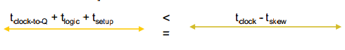
Time to propagate a valid (no violations) signal at D2, to D3, counting from the clock edge at Flipflop2,
is invariably = tclock-to-Q + tlogic.
And for Flipflop3 to latch it, this signal has to be maintained at D3 for tsetup time before the clock tree sends the next positive edge of the clock to Flipflop3.
Fig: Following figure shows the condition of setup violation
To prevent setup violations..........
Fig: Following figure shows that how data should propagate without hold violation
For D2 to be able to send its signal to Q2, it must be left unchanged for thold time after a clock edge. That is, during this time, a signal from D1 should not be able to race through the combinational logic Comb1 and make it to D2.
Fig: Following figure shows the condition of hold violation
Therefore, to make sure the signal is HELD properly at the input of Flipflop2 without the
input of the previous Flipflop (D1) racing through
To prevent from hold violations:


No comments:
Post a Comment