Clock skew is a phenomenon in synchronous circuits in which the clock signal (sent from the clock circuit or source or clock definition point) arrives at different components at different times.
due to
Figure: Clock Skew
there are two types of clock skew
Negative skew is occurs when the receiving register gets the clock tick earlier than the sending reg
Zero clock skew refers to the arrival of the clock tick simultaneously at transmitting and receiving reg
Skew can be caused two types of violation
When the clock travels slower than the path form the one reg to another allowing data to penetrate two registers in the same clock tick, or maybe destroying the integrity of the latched data. this is called hold violation because the previous data is not held long enough at the destination flop to be properly clocked though.
if the destination flop receives the clock tick earlier than the source flop- the data signal has that much less time to reach the destination flop before the next clock tick, if it is fails to do so,a setup violation occurs, so called new data was not set up and stable before the next clock tick arrived.
Useful Skew
clock skew can also benefit a circuit by decreasing the clock period locally at which the circuit will operate correctly, it means skew add more margin to meet setup. that is called useful skew
for each source register and destination register connected by a path. so, following setup and hold inequalities must be obeyed.
for setup,
T(clock period) > = T(reg) + Path dealy(max) + J(jitter) + S(setup time) - Skew
for Hold,
Skew <= T(reg) + Path delay(min) - J(jitter) - H(hold time)
Positive skews are good for fixing setup violation, but can cause hold violation
Negative skew can help hold violation, but can cause setup violation
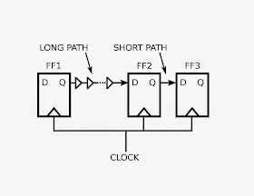
In the zero skew circuit, a long path goes form FF1 to FF2, and short path, from FF2 to FF3,
here, Path FF2 -> FF3 path is close to having a hold violation: if small amount of extra clock delay occurs at FF3, this could destroy the data at D input of FF3 before clock arrives.
for clock skew.
A small amount of extra delay is added before FF2's clock input. with the care the extra delay relaxes the setup constraint for the FF1->FF2
here, for FF1->FF2 operates less than what required for zero skew.
so, some intentional skew helps in proper functioning of circuit,
NOTE: in above example, circuit is closer to malfunctioning- a small amount of positive clock skew for the FF2-> FF3 pair will cause hold violation, whereas the intentional skew(useful skew) circuit helps to meet the setup and hold constraints
due to
- wire-interconnect length
- temperature variations
- capacitive coupling
- material imperfections and
- differences in input capacitance on the clock inputs
Figure: Clock Skew
there are two types of clock skew
- Negative skew
- positive skew
Negative skew is occurs when the receiving register gets the clock tick earlier than the sending reg
Zero clock skew refers to the arrival of the clock tick simultaneously at transmitting and receiving reg
Skew can be caused two types of violation
- Setup violation
- Hold violation
When the clock travels slower than the path form the one reg to another allowing data to penetrate two registers in the same clock tick, or maybe destroying the integrity of the latched data. this is called hold violation because the previous data is not held long enough at the destination flop to be properly clocked though.
if the destination flop receives the clock tick earlier than the source flop- the data signal has that much less time to reach the destination flop before the next clock tick, if it is fails to do so,a setup violation occurs, so called new data was not set up and stable before the next clock tick arrived.
Useful Skew
clock skew can also benefit a circuit by decreasing the clock period locally at which the circuit will operate correctly, it means skew add more margin to meet setup. that is called useful skew
for each source register and destination register connected by a path. so, following setup and hold inequalities must be obeyed.
for setup,
T(clock period) > = T(reg) + Path dealy(max) + J(jitter) + S(setup time) - Skew
for Hold,
Skew <= T(reg) + Path delay(min) - J(jitter) - H(hold time)
Positive skews are good for fixing setup violation, but can cause hold violation
Negative skew can help hold violation, but can cause setup violation
Figure :1
Figure 1 show a situation where clock skew can benefit a synchronous circuitIn the zero skew circuit, a long path goes form FF1 to FF2, and short path, from FF2 to FF3,
here, Path FF2 -> FF3 path is close to having a hold violation: if small amount of extra clock delay occurs at FF3, this could destroy the data at D input of FF3 before clock arrives.
Figure 2
Figure 2 shows how the problem can be fixedfor clock skew.
A small amount of extra delay is added before FF2's clock input. with the care the extra delay relaxes the setup constraint for the FF1->FF2
here, for FF1->FF2 operates less than what required for zero skew.
so, some intentional skew helps in proper functioning of circuit,
NOTE: in above example, circuit is closer to malfunctioning- a small amount of positive clock skew for the FF2-> FF3 pair will cause hold violation, whereas the intentional skew(useful skew) circuit helps to meet the setup and hold constraints


better give some example of positive skew and negitive skew with values and all
ReplyDeleteIt's relative to the FF you observe.
Delete